Design an 8-bit Adder Using Two 4-bit Adders
| Tutorial Project: Designing 8-bit Hexadecimal Adders With Digital Data Buses |
 |
| Objective: In this project, you will use 4-bit digital adder devices to build 8-bit adders with two and three hexadecimal inputs. |
| Concepts/Features:
|
| Minimum Version Required: All versions |
| ' |
What You Will Learn
In this tutorial you will use commercial digital parts to build two-output and three-output digital adders. You will learn how to combine or split digital data bus lines. You will also learn how to define and work with hexadecimal data.
Multi-Bit Digital Data in RF.Spice A/D
RF.Spice A/D allows you to define single-bit or multi-bit digital input data. In addition, you can define your digital input and output data in either of decimal or hexadecimal (base-16) formats. You have to specify the number of bits and the representation format in the property dialog of the digital input or output.
| The property dialog of a digital input. | The property dialog of a digital 0utput. |
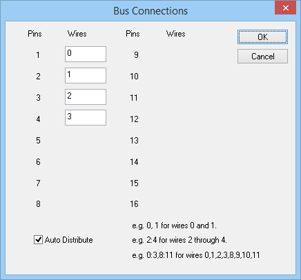
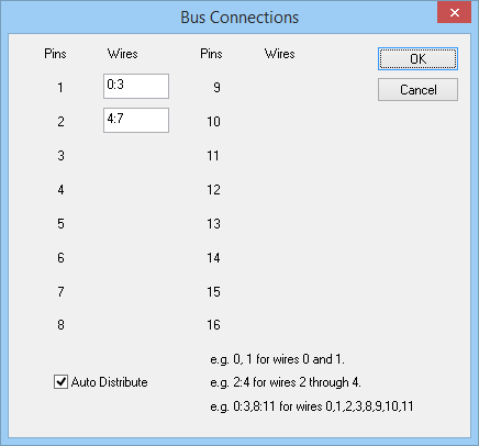
So far in all the previous digital tutorial lessons, you used single-bit binary data at the input or output of your digital circuits. RF.Spice A/D provides digital data buses along with a number of bus splitter or bus combiner devices for bundling multiple digital wire together. Using digital buses you can avoid cluttering you schematic with a large number of digital wires. You can choose from 1:2, 1:3, 1:4 and 1:8 bus splitters or from 2:1, 3:1 , 4:1 or 8:1 bus combiners. The figures below show the property dialog of digital bus combiners and splitters.
| The property dialog of a 4:1 digital bus combiner carrying 8-bit data. | The property dialog of a 1:2 digital bus splitter carrying 8-bit data. |
Building a Two-Input 8-Bit Adder
The following is a list of parts needed for this part of the tutorial lesson:
| Part Name | Part Type | Part Value |
|---|---|---|
| In1 - In2 | Digital Input | 8-bit Hexadecimal |
| Out1 - Out2 | Digital Output | Hexadecimal |
| A1 | 74LS83N 4-bit Digital Adder: Section A | Defaults |
| A2A | 74LS83N 4-bit Digital Adder: Section B | Defaults |
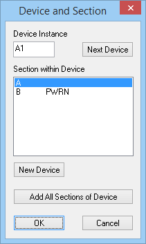
You can find the digital adder parts 74LS83N in the Parts Bin. Open its Function tab and select the menu item Digital Components > Adder.... This commercial product has two devices in the same package marked sections A and B. When you place the first part A1, the program asks you which section of the package you want to place. Select "Section A". If you use your keyboard's Space Bar to duplicate the last placed part, it will automatically place the section of the package.
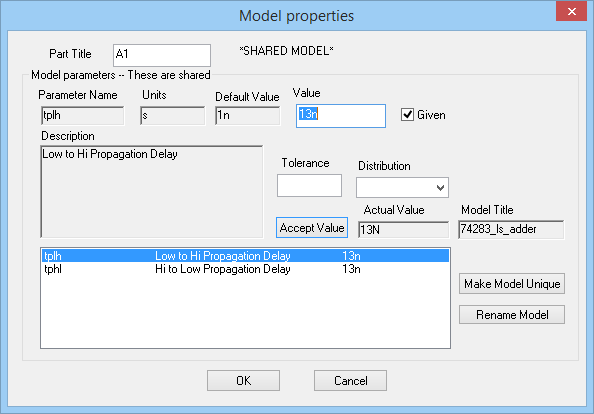
| The "Device & Section" dialog. | The property dialog of the commercial digital adder 74LS83N. |
In this tutorial lesson, you will use two 4-bit 74LS83N adders to build an 8-bit adder for summing two 8-bit hexadecimal inputs. You will define two hexadecimal digital outputs, one for the sum and the other for the carry-over. Place and connect the parts as shown in the figure below. You need two 1:2 bus splitters, four 1:4 bus splitters, two 4:1 bus combiners and one 2:1 bus combiner as shown in the figure. Ground the carry-in pins of the two adders. In RF.Spice's digital simulation mode, a grounded pin means a "0" or "Low" binary state.
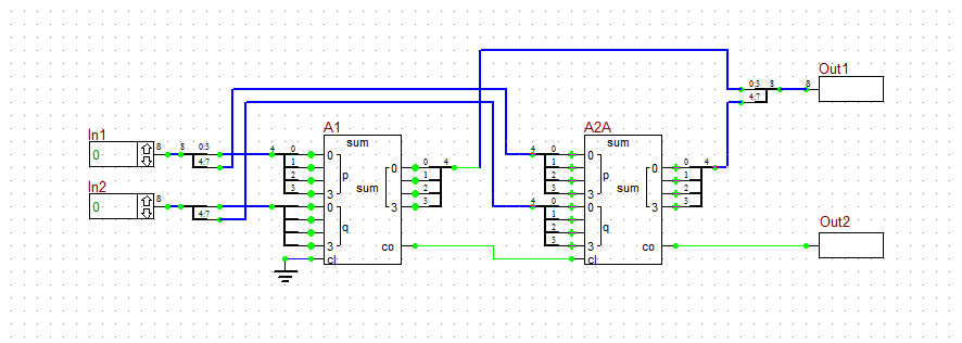
The schematic of the 8-bit digital adder using two 4-bit 74LS84N devices.
Testing Your 8-Bit Adder Circuit
You are going to run a live digital simulation to test your circuit. Set the Step Time to 40ns. Step through the circuit. Initially the two inputs are 0, and so are the two outputs.
Change the inputs one by one at each time step according to the table below:
| Case | In1 (HEX) | In1 (DEC) | In2 (HEX) | In2 (DEC) | out1 (HEX) | out1 (DEC) | out2 (HEX) | out2 (DEC) |
|---|---|---|---|---|---|---|---|---|
| 1 | 0 | 0 | 0 | 0 | 0 | 0 | 0 | 0 |
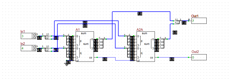
| 2 | 3 | 3 | 4 | 4 | 7 | 7 | 0 | 0 |
| 3 | 1C | 28 | 6 | 6 | 22 | 34 | 0 | 0 |
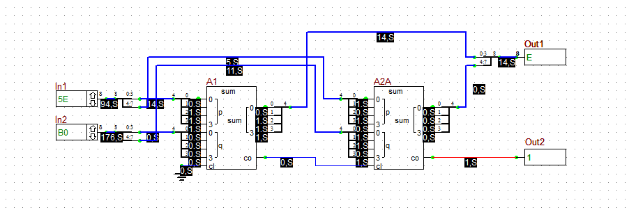
| 4 | 5E | 94 | B0 | 176 | E | 14 | 1 | 256 |
The figures below show the binary state of the circuit for cases 2, 3 and 4. The above table summarizes the results.
| | At the end of a live digital simulation, you can clean up your schematic editor by selecting Clear Schematic State from the View Menu. |
| The outputs of the 8-bit digital adder when In1 = 3 and In2 = 4. |
| The outputs of the 8-bit digital adder when In1 = 1C and In2 = 6. |
| The outputs of the 8-bit digital adder when In1 = 5E and In2 = B0. |
Building & Testing a Three-Input 8-Bit Adder
The following is a list of parts needed for this part of the tutorial lesson:
| Part Name | Part Type | Part Value |
|---|---|---|
| In1 - In3 | Digital Input | 8-bit Hexadecimal |
| Out1 | Digital Output | Hexadecimal |
| A1, A2A, A3, A4A | 74LS83N 4-bit Digital Adder: Section A | Defaults |
| A5 | 74LS86N XOR Gate | Defaults |
| A5 | 74LS08N AND Gate | Defaults |
In the last part of this tutorial lesson, you will use two 8-bit adder circuits of the type you build earlier to build a three-input 8-bit adder. In this case, rather than sending out a carry-over bit, you will combine it with the sum part and create a 10-bit digital output. The resulting circuit will be able to generate large sums up to "FFF" or the decimal equivalent 4095. Place and connect all the parts as shown in the figure below. You can copy and paste a large part of the two-input adder circuit of the previous section to save time.

The schematic of the 8-bit digital adder using two 4-bit 74LS84N devices.
With the same Step Time of 40ns, run a live digital simulation and verify the performance of your three-input digital adder circuit using the following hexadecimal inputs:
| Case | In1 (HEX) | In1 (DEC) | In2 (HEX) | In2 (DEC) | In3 (HEX) | In3 (DEC) | out1 (HEX) | out1 (DEC) |
|---|---|---|---|---|---|---|---|---|
| 1 | 0 | 0 | 0 | 0 | 0 | 0 | 0 | 0 |
| 2 | 2 | 2 | 6 | 6 | A | A | 12 | 18 |
| 3 | FF | 255 | 1B | 27 | A0 | 160 | 1BA | 442 |
| 4 | C8 | 200 | C8 | 200 | C8 | 200 | 258 | 600 |
The figures below show the binary state of the circuit for cases 2, 3 and 4.
| The outputs of the 8-bit digital adder when In1 = 2, In2 = 6 and In3 = A. |
| The outputs of the 8-bit digital adder when In1 = FF, In2 = 1B and In3 = A0. |
| The outputs of the 8-bit digital adder when In1 = In2 = In3 = C8. |
Back to RF.Spice A/D Tutorial Gateway
Design an 8-bit Adder Using Two 4-bit Adders
Source: http://www.emagtech.com/wiki/index.php/Advanced_Tutorial_Lesson_8:_Designing_8-bit_Hexadecimal_Adders_With_Digital_Data_Buses



0 Response to "Design an 8-bit Adder Using Two 4-bit Adders"
Post a Comment